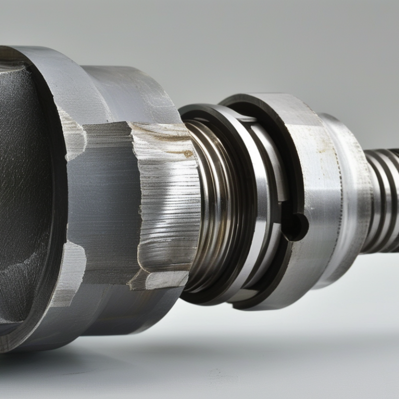
| Basic definition | A threaded shaft end is the portion of a cylindrical shaft that contains helical threads, normally on the outside diameter. | Allows components such as nuts, hubs, bearings, collars, or couplings to be secured to the shaft. | The threaded section should be concentric with the shaft axis and manufactured with a suitable surface finish. |
| Common thread form | Metric ISO 60-degree V-thread, commonly specified as M6 × 1.0, M8 × 1.25, M10 × 1.5, M12 × 1.75, M16 × 2.0, or M20 × 2.5. | Provides standardized compatibility between the shaft end and mating internally threaded parts. | The designation gives the nominal thread diameter in millimetres followed by the pitch in millimetres. |
| Nominal diameter | Typical external-thread sizes range from approximately 6 mm to 20 mm in light- and medium-duty assemblies. | Influences the tensile, shear, and torsional capacity of the threaded connection. | The effective load capacity is lower than that of a plain shaft with the same outside diameter because material is removed to form the thread. |
| Thread pitch | Typical coarse metric pitches include 1.0 mm for M6, 1.25 mm for M8, 1.5 mm for M10, 1.75 mm for M12, 2.0 mm for M16, and 2.5 mm for M20. | Determines axial movement per revolution and affects tightening speed, self-locking behavior, and thread strength. | Fine-pitch threads may provide greater adjustment precision and improved resistance to loosening, but they require closer control of contamination and damage. |
| Threaded length | Common threaded lengths are approximately 1 to 2 times the nominal diameter, depending on the load and application. | Provides sufficient engagement for transferring axial and tightening loads. | Actual engagement length must be calculated from load, material strength, thread class, and the strength of the mating nut or component. |
| Thread engagement | For steel-to-steel connections, an engagement length near one nominal diameter is often used as an initial design reference; softer materials generally require more. | Controls resistance to thread stripping and pull-out. | This is a preliminary guideline, not a universal rule. Engineering calculations are required for highly loaded or safety-critical joints. |
| Thread tolerance class | Metric external threads are commonly specified with classes such as 6g, while internal threads may use a class such as 6H. | Controls the fit, clearance, interchangeability, and assembly torque of the mating parts. | The selected tolerance should allow assembly without excessive play while preventing binding under normal operating conditions. |
| Thread runout and relief | A relief groove or runout area may be provided between the threaded portion and the unthreaded shaft. | Allows the cutting tool to exit cleanly and enables the mating component to seat against a shoulder. | Adequate relief reduces incomplete threads and helps prevent stress concentration at the thread termination. |
| Shoulder and seating surface | Many threaded shaft ends include a shoulder, spacer seat, or machined locating surface adjacent to the threads. | Positions the mounted component axially and transfers clamping or reaction forces. | The shoulder face should be square to the shaft axis when accurate bearing or hub alignment is required. |
| Typical shaft-end components | Nuts, locknuts, washers, spacers, retaining collars, bearings, hubs, sprockets, pulleys, and couplings. | Creates a removable connection without welding, permanent bonding, or complex external clamps. | Use a washer or dedicated seating face when the mating component could be damaged by the nut or tightening force. |
| Primary loads | Axial tension, axial compression, preload, torsion, bending, and localized bearing loads may act on the threaded end. | Allows the joint to retain components and resist movement during operation. | Threads are especially sensitive to combined loading and bending near the first engaged thread; avoid using a threaded section as a high-bending region when possible. |
| Locking methods | Common methods include a prevailing-torque nut, locknut, castellated nut with a retaining pin, tab washer, thread-locking compound, or safety wire. | Reduces the risk of loosening caused by vibration, cyclic loading, or changes in temperature. | The locking method must be compatible with the service temperature, lubrication, maintenance requirements, and required disassembly frequency. |
| Common materials | Carbon steel, alloy steel, stainless steel, and aluminium alloys are frequently used for shafts and threaded ends. | Material selection determines strength, corrosion resistance, weight, wear resistance, and machinability. | When using dissimilar metals, consider galvanic corrosion, thread galling, and the need for suitable lubrication or surface treatment. |
| Surface protection | Possible treatments include oiling, zinc-based coatings, black oxide, passivation, or other application-specific finishes. | Protects the threaded end from corrosion and preserves the fit between mating threads. | Coating thickness can alter thread fit and tightening behavior, so coated threads should be specified and inspected accordingly. |
| Manufacturing methods | Threads may be produced by single-point turning, die cutting, thread milling, or thread rolling. | Creates the helical profile needed for the mating connection. | Thread rolling can improve fatigue performance by displacing material and producing beneficial surface properties, while cutting methods are flexible for low-volume or large-diameter work. |
| Inspection requirements | Typical checks include nominal diameter, pitch, thread length, runout, visual damage, and fit with a calibrated mating gauge. | Confirms interchangeability and helps prevent assembly failure. | For critical assemblies, inspect thread form, concentricity, surface defects, hardness, and dimensional compliance with the specified drawing or standard. |
| Applicable thread standards | Metric threads are commonly defined using ISO 261 and ISO 965; unified inch threads may be specified using ASME B1.1. | Provides consistent thread geometry, dimensions, tolerances, and interchangeability. | The drawing should state the thread standard, nominal size, pitch or threads per inch, tolerance class, handedness, and threaded length. |
| Right-hand and left-hand threads | Right-hand threads are standard; left-hand threads are used where rotation could loosen a conventional right-hand thread. | Helps maintain the connection under a known direction of rotation. | Left-hand threads must be clearly marked because they are not interchangeable with standard right-hand mating parts. |
| Key advantage | Provides a compact, strong, adjustable, and removable method of retaining parts on a shaft. | Supports maintenance, replacement, preload adjustment, and controlled axial positioning. | Correct thread specification, adequate engagement, proper tightening, and suitable locking are essential for reliable service. |